Adding PPS to a cheap USB GPS stick

Yesterday I came across this interesting video of Eric S. Raymond giving a talk. About 40 minutes in He talks of a fascinating project to develop and have produced a USB GPS dongle with PPS (Pulse per second) support  to provide a decent Timing reference for use with NTP.

Eric ‘ESR’ Raymond presenting to the Philadelphia Area Java Users’ Group from April 18, 2012

This then lead me to a couple of blog posts by ESR

http://esr.ibiblio.org/?p=4335

and

http://esr.ibiblio.org/?p=4281

This caused me to take another look at GPSD in the context of feeding NTP and also prompted me to try a USB – serial adapter with one of my PPS enabled GPS units.

The results were really good and it was simple to set-up on fedora 16. To get it working it’s just a matter of ensuring GPSD starts up and adding 4 lines to the ntp.conf

#gpsd
server 127.127.28.0 minpoll 4 maxpoll 4
fudge 127.127.28.0 time1 0.420 refid GPS

server 127.127.28.1 minpoll 4 maxpoll 4 prefer
fudge 127.127.28.1 refid PPS

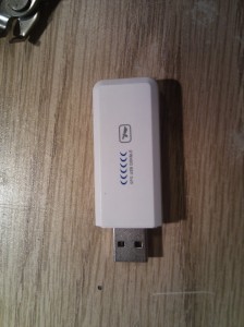
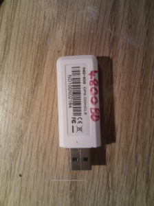
This got me thinking about a cheap little GPS dongle that I had on my desk.  according to dmesg it uses the prolific pl-2303hx USB to serial bridge controller and this chip does support the DSR line.

Time to take it apart..

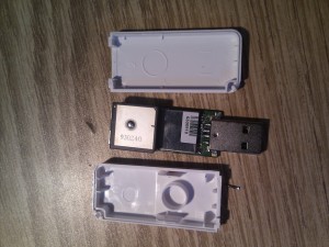
The GPS Dongle

Cover off
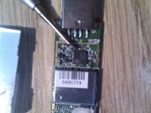
Cover off


All the fun stuff is under the antenna and the tin can.

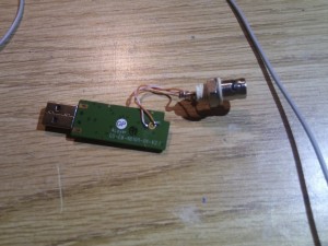
To find the PPS output of the GPS module I needed to fit a temporary antenna connection since once the can is removed so is the on-board antenna.

Inside the shield, This is the PL-2302HX, in a rather small QFN package

Temporary antenna connection. A BNC is perhaps a bit large.


With this done it’s time to locate the PPS output with a scope. It turned out to be on my module, the second pin from the left on the USB side of the GPS module.

The DSR pin was located from the PL-2303HX data-sheet, It turned out that this board had a little 4k7 resistor in place to pull this line high. This would have to be removed and as a bonus this left me with a nice place to connect the blue wire.

At this point I tested again and saw that GPSD was feeding good looking PPS data to ntpd.

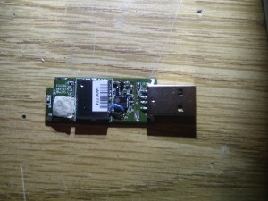
Blue wire installed


Time to put it back together

Back together with some soldering and a few drops of superglue


The end result is that the GPS stick still provides navigation data and now has a high quality PPS output as well.



Posted in GPS, ntp, timenut | 15 Comments

A new Toy

On Thursday I received my field test version of the KPA500, Serial Number #15
It’s the soon to be released 500W solid state linear amplifier from Elecraft covering the HF and 6m bands

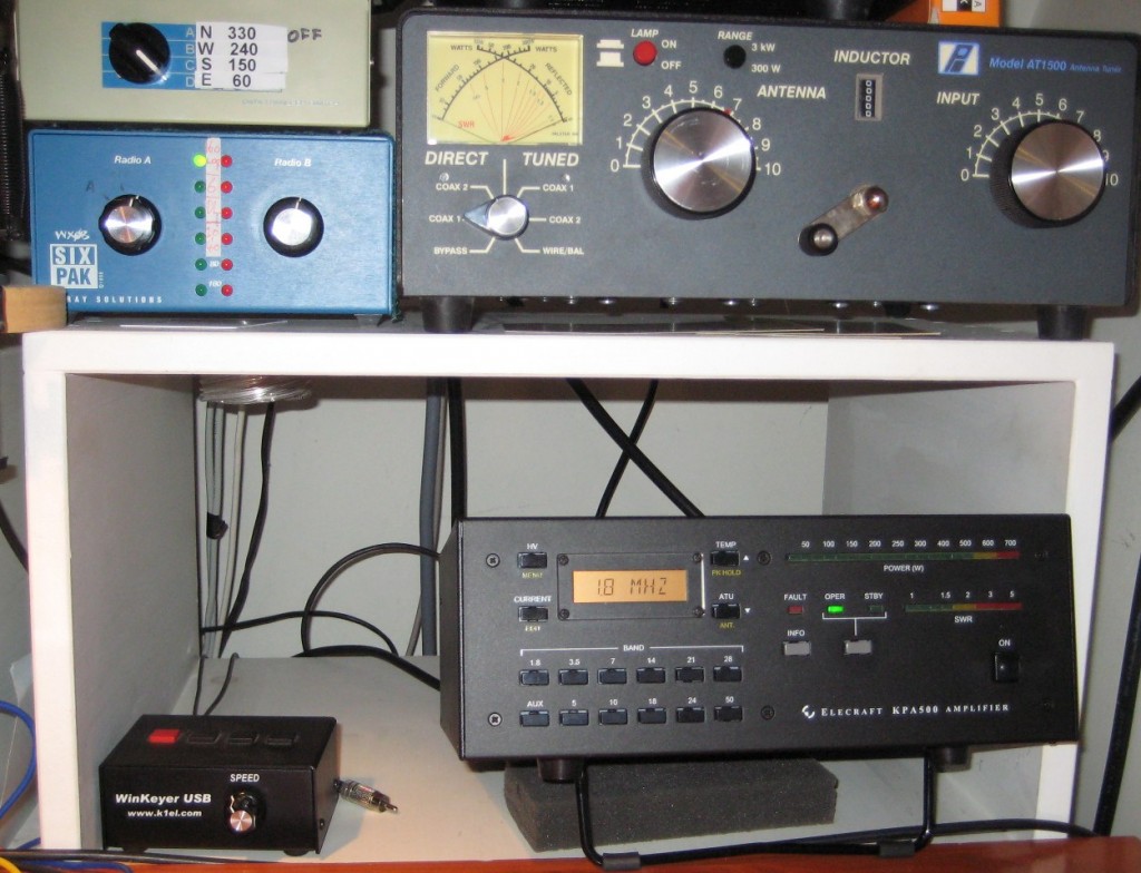
KPA500

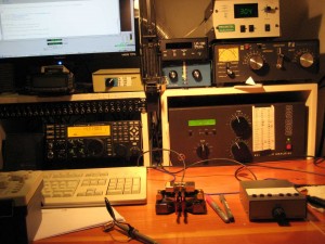
This picture shows the KPA500 in the place where My ACOM1000 Normally goes, The ACOM just fits in this space.

This is my first experience with a solid state amplifier and I must say it’s been smooth sailing so far.  it’s certainly very nice to have an amplifier that has no 3 minute warm up period. Just switch on and it’s ready to go. I have had a few hundred QSO’s on it already and have not run into any issues so far

The amp is the same size as the K3 and uses an internal linear Power supply so it’s quite a bit heaver than the K3, weighing in at around 13.5Kg (including shipping materials, see comments)

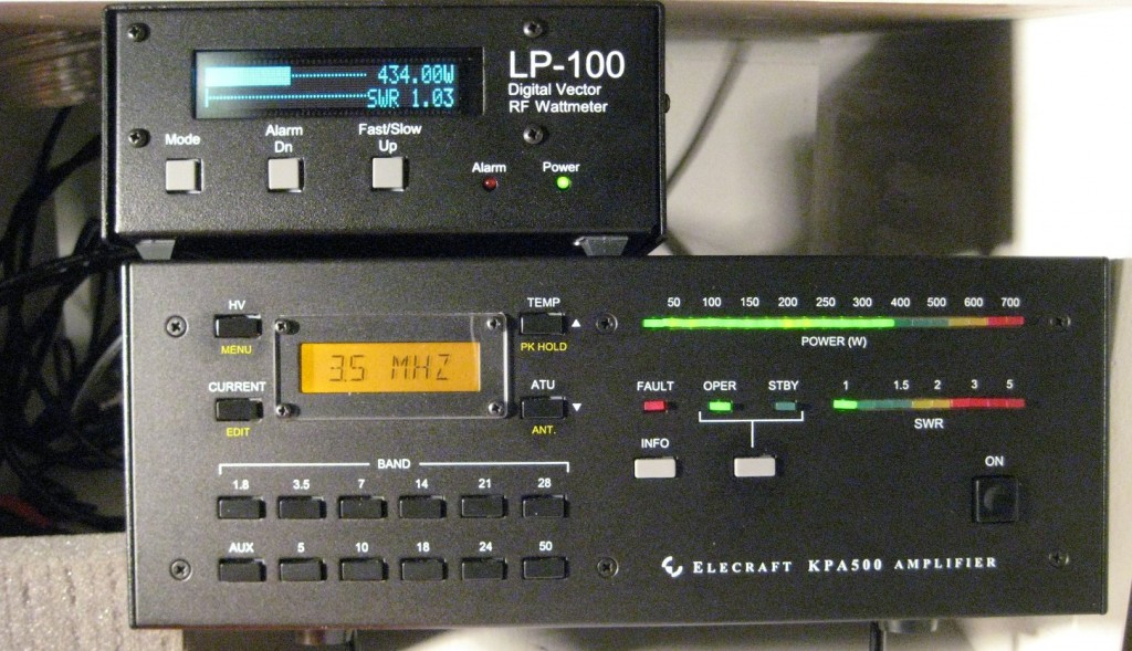
The amplifier is rated to develop 500W into loads that are 2:1 SWR or better, band switching is automatic, it simply senses the  RF and switches band as needed, this happens nearly instantaneously, before you have even completed the first ‘dit’ it has switched in the appropriate bandpass filters . The metering is very effective and compares reasonably well with my LP100 external power meter.

The amplifier produces the Irish legal limit of 400W out for around 20W drive

Hooking it up with the K3 requires  RF connections, Power (120 or 230V) and a PTT connection. No need to hook up ALC, if you overdrive the amp it will automatically switch in an attenuator and flash the fault LED  to protect it’s self, if you persist in over driving the amp will take it’s self off line.On the rear there are also an ALC input and RS232 for firmware updates. The metering is extensive, the LCD display can show various parameters such as the Heat-sink temperature, ‘HV’ voltage, PA current, SWR, Power and defaults to displaying the current operating band.

transmit/receive switching is with PIN diodes it’s full QSK and silent, The internal fan comes on in 4 stages and is reasonably quiet, the slowest speed does not engage until the amp’s heatsink warms up to 45 degrees C so for light duty operation and in standby or receive the amp is utterly silent.

Into a dummy load the KPA500 will generate up to 650W before it brings in the attenuator, a look at the spectral purity of the output on my SDR-14 software defined receiver shows a very clean output signal.

The KPA500 has sophisticated microprocessor controlled protection systems built in and is designed with very ample safety margins. Mechanically it is very well built and sturdy. Internally there are Transformer taps covering 100-120V and 200 to 240V.  This would be an ideal amplifier for Dxpeditions and IOTA activations.

It looks like my ACOM1000 may soon be for sale

Posted in k3, KPA500 | 8 Comments

A pleasant surprise in the post

Posted in Contesting | Leave a comment

An interesting Problem

Recently I Dug out an old headset that I had leftover from my Pro-audio days. It’s A Beyerdynamic DT-109 which is a very nice set of Headphones with a good quality Hyper-cardoid microphone capsule. Ideal for rejecting shack noise and with a response curve well suited for Good Quality communications audio. Data sheet as a PDF here

The first issue I had was that the audio level out of the DT-109’s microphone is rather low so I constructed a premap based on this Design. This is powered by the 5V bias that is available from the K3 for driving Electoret condenser microphones. I constructed this preamp on a bit of Stripboard and mounted in a small herb tin I stole from the kitchen.

This worked very well, at least until I turned my amp on.  With my Acom1000 on, even in standby I was hearing a lot of Hum. At first I though it might be down to a ground loop problem, I had taken care to ensure that the ground on the radio side of the preamp was connected at the point where the wire enters the tin but the Microphone side floats above ground and is decoupled by a Capacitor (C1) first I tried a larger value to no avail, Then I tried adding a 1:1 audio transformer and grounding the headphone side. This made matters much Worse.

Then the penny dropped! The issue was due to the magnetic field from the Power supply of the amplifier.  Where I had the amplifier positioned was around 1metre away from the the Microphone element when I was sitting in the operating position and the microphone had it’s back side facing the amplifier, Maximising it’s sensitivity to the magnetic field

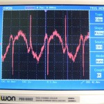
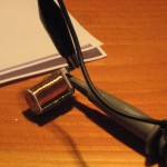
I hooked up an old solenoid coil to my portable scope and did some sniffing around to get an idea of the magnitude of the field. I discovered that the field was pretty intense in the vicinity of My K3s and their transformer coupled Audio lines so it seemed prudent to relocate the amplifier. Interestingly the Magnetic Field contained a lot of harmonic energy, Due I suspect to the rectifiers in the Power supply. The power supply is contained in the right-hand side of the Acom1000 so the answer was to move the amplifier from the left  of the operating position to the Right. Not an ideal location for ventilation in my shack but  I had some aluminium Ducting that I was able to use to improve the exhaust airflow

With the amplifier on the right the power supply is a little further away from the microphone element but this position also means that the  side of the microphone capsule is pointing towards the Amplifier and in this position the element is less susceptible to picking up the Magnetic field. This position also places the  k3’s Line in / out transformers a lot further away from the field which should  prevent issues with Digital modes.

The DT-109 now works wonderfully with the K3, I use the following EQ settings

50Hz  -16, 100Hz -16, 200Hz -8, 1.6KHz +3

The New Shack layout

73

Brendan EI6IZ

Posted in Audio, k3, shack | Leave a comment

K3 Line output plots

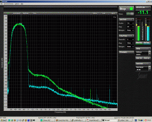
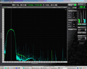
I took a couple of plots of the K3’s Line output compared to the Headphone output

For these plots the K3 was connected to a wideband noise generator. measurements were made with my Delta 44 soundcard

The line out is in green. the Blue trace is the headphone output with the volume set to match the level of the line out

The first plot is with the line output level set to 100, the second plot is with the line output level set to 5

Posted in Audio, k3 | 3 Comments

KRX3 the elecraft K3 Sub Receiver

My KRX3 arrived yesterday and after about 4 hours of work It was fitted into my K3. For those of you that don’t already know The KRX3 adds a second receiver of equal specification to the primary receiver to the K3

Generally sub receivers are useful to help find out where the dx station is listening in the pileup, to search for multipliers whilst ‘running’ in a contest or to monitor a second band.

The K3 with the KRX3 fitted has another ‘neat trick’ up it’s sleeve. If the KRX3 is configured with the same filters in at least some of the slots as the primary receiver it can be used for Dual antenna diversity reception. In this mode the Sub RX tracks the tuning of the main RX. I have been using diversity reception for a number of years for tropical band broadcast Dxing with my Racal RA-3702 however the K3 is the first amateur transceiver I have used that is actually capable of doing diversity reception well.

Icom’s Flagship 7800 fails miserably in diversity on two counts. Firstly the main and Sub RX have a small but constant frequency offset making it very tiring to listen to, secondly the tuning of the main and sub receivers cannot track.

On the Elecraft k3 tuning tracks both receivers (when linked) RIT also applies to both receivers making the k3 very easy to use in diversity mode.

Diversity holds a lot of promise for weak signal DXing where using 2 separate antennas can help reduce the impact of fading, QRM and noise

Diversity is also very useful for enhancing the ability to pull individual calls out of large pileups

K3 30M Diversity is a 5 minute audio clip of the K3 in Diversity mode. For a better idea of how useful this is listen with headphones on.

here is the YR2TOP beacon on a noisy 160m with K9AY loops on the left and a beverage on the Right
filter bandwidth is 150hz this time
160m_beacon_k3

Here is a clip of an SSB pileup on 20m Here too diversity reception helps to separate the callers
k3_20mssb_diversity

Posted in Audio, k3 | 11 Comments

Cheap Headset

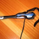
One of the nice things about the elecraft K3 is the support that it has for a very wide range of microphones. The rear panel mic connector is directly compatible with computer headsets once the bias voltage is enabled to power the electret condenser element.

My normal headset is a home brew one based on the bias circuit that is normally used in Icom hand mics. This simple circuit is published in the user manuals for most modern Icom Radios. The manuals can be found on line on the Icom website.

Recently, however I have been using a little headset that I bought on Ebay for 1 pound Sterling ( about 2 US dollars.)
I have been getting truly fantastic audio reports on this headset when used with the K3. It’s a little bit flimsy but it’s very light and easy to wear, It simply loops over one ear.

Vox on the K3 is fantastic but I prefer to use a footswich for PTT control.

Lots of Ebay vendors have similar products and any computer store will sell you a ‘skype’ headset. Before you spend ‘proper’ money on expensive ham radio branded products, try a cheap computer headset. You may be very pleased with the results.

Posted in k3, shack | 1 Comment

Progress

Last October I was at an event organised in Clifden to commemorate 100 years of Commercial radio. On October the 17th 1907 the worlds first commercial point to point wireless link opened for service between Clifden in Ireland and Glace Bay, Nova Scotia. This link remained in service until the Clifden station was destroyed in 1922
You can read some background on the type of transmitter used at Clifden on
OZ6GH’s pages

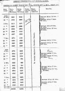
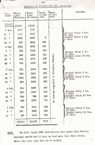
I recently came across traffic logs for the first few months of the station’s operation, these show that in the first ten months of operation that 129,614 words were sent and 116,633 words received over the radio link, a total of 246,247 words exchanged, approximately 820 words a day.

I expect that in the later years of operation that the data rates were much improved but even assuming that 12 words per minute could have been maintained for 18 hours per day, every day, this works out at approximately 331 Megabytes of data transmitted during the entire lifespan of the station

A little over 100 years later my company commissioned a new 155 Mbs wireless point to point link to connect to our Internet transit provider.
331 Megabytes of data can pass over this link in around 17 seconds. This link is just a tiny sliver of today’s telecoms infrastructure. What a long way we have come in the last 100 years.

Posted in Hisory | Tagged , , , | 1 Comment

The Elecraft K3 and an Audio Patchbay

I have had the very nice elecraft K3 here in the shack since November 2007. It’s an absolutely fantastic radio and it also has a lot of I/O connections on it’s crowded rear panel.
Elecraft for user convenience sake make all the audio connections using 1/8″ Jack sockets. This is of course very handy in that using a single standard audio connector makes for quick and easy reconfiguration. Unlike DIN or Mini-din connectors 1/8″ Jack plugs are available almost everywhere too.
The downside is that in a permanent shack setup reaching around to the crowded rear panel may be tricky and with the tight spacing it’s easy to remove or losen the wrong mini-jack plug as they do not have much holding force.

I have made access to the K3’s wide range of I/O connectors much easier by connecting all of the Audio keying and PTT lines via a 1/2 Normalised balanced jack Patchbay.

1/2 Normalised is particularly usefull for this purpose in that you can plug into the upper (black) Socket and be connected in parallel with the normal signal path. if you plug into the Lower socket you interupt the normal signal path.
Parallel connections are usefull if you wish to route the line out audio to two devices, or hook up two Morse keys.
The interupting connection is usefull for connecting a different microphone as you would not want to have 2 microphones connected in parallel

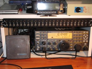
K3 with Pathcbay

One of the problems with patchbays is keeping track of all the connections. I do this by using a simple wordprocessor table which looks like this (click on image to zoom in)

As you can see I have plenty of unused inputs for future use.

Patchbays are easily available new or second hand at low cost on e-bay and make a most usefull addition to the shack.

Posted in k3, shack | Tagged , , | 6 Comments

A Blog

Well I resisted Having a blog for a good number of years now, Finally it’s time to give in and follow the herd

Posted in Uncategorized | Tagged | 1 Comment